The Large Binocular Telescope uses an elevation over an azimuth mounting. The elevation optical support structure moves on two large C-shaped rings and the compact azimuth platform transmits the loads directly down to the pier. The two 8.4 meter (331 inch) diameter primary mirrors are mounted with a 14.4 meter center-center separation. By using swing arms to rotate the secondary mirrors and their supports, it is possible to switch the telescope from one mode of observation to another very quickly. The short focal length of the primary mirrors (F/1.142) permits a compact, and therefore quite stiff telescope structure. Following are some of the characteristics of the telescope structure:
Telescope
- Telescope Structure: model A’, platform design
- Support Spacing: 2 “C” rings on 10 meter centers
- Pier Diameter: 13 meters for azimuth track
- Telescope Height: ~ 25 meters at elevation axis (30 m above bedrock)
- Building Height: ~ 40 meters at roofline
- Support of Telescope: hydrostatic pads
- Drive Mechanism: gear and pinion
- Telescope and Drive Stiffness Goal: locked rotor frequency > 8 Hz
- Vibration Specification: < 0.025 m amplitude above 8 Hz
- Encoders: strip type
- Telescope Moment of Inertia: approximately 1.0*107 Kg m2 (both axes)
- Telescope Mass: approximately 580 metric tons
- Maximum Angular Speed: 1.5 degrees/second
- Maximum Angular Acceleration: 0.3 degrees/second2
- Maximum Angular Acceleration: 0.3 degrees/second2
- Error Budget: telescope and optics to match r0 = 45 cm atmosphere
- Implied Image Size from Telescope = 0.22 arcsecond FWHM
- Short Term Tracking Specification: 0.03 arcsecond rms motion (5 seconds)
- Whole Sky Pointing Specification: 0.3 arcsecond rms
- Wind Speed for Pointing and Tracking Specs: 24 km/hr
- Maximum Operating Wind Speed: 80 km/hr
- Survival Wind Speed (closed): 225 km/hr
- Primary Mirror Aluminizing: on-board the telescope
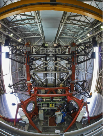
The swing arms are the three black structures hanging on each side of the mount above the primary mirrors. From top to bottom
– The adaptive secondaries (in the beam on both sides)
– The Large Binocular Cameras (out of the beam on both sides)
– The tertiary flats (out of the beam on the left, in the beam on the right)
Optics
Two Primary Mirrors
- Primary Spacing: 14.417 meter center-to-center
- Primary Physical Diameter: 8.417 meter
- Primary Focal Ratio: F/1.142
- Central Hole Physical Diameter: 0.889 meter
- Primary Figure: parabolic
- Primary Construction
- cast borosilicate honeycomb
- 28 mm faceplate thickness
- edge thickness 894 mm, plano-concave
- Primary Mirror Mass: approximately 16 metric tons each
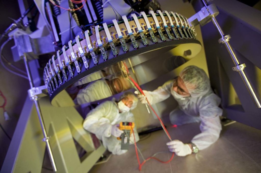
Two Adaptive Secondary Mirrors
- Infrared Gregorian, F/15
- Interchange: swing arm
- Mirror diameter: 0.911 m (undersized secondary)
- Mirror thickness: 1.6 mm
- Infrared field-of-view: 4 arcminutes (unvignetted at primary)
- Optical field-of-view: 10 arcminutes (vignetted at secondary)
- Asphere: -0.7328
- Focal ratio of full-aperture parent: F/14.72
- Back focal distance: 3.050 m
Two Tertiary Flats
- Interchange: swing arm
- Minor axis diameter: 50 cm (45 cm minimum)
- Major axis diameter: 64 cm
- Location: 2.25 m above primary vertex
- F/15 field-of-view: 8 x 4 arcminutes (before tertiary vignettes)
- Role: rotate to switch between the LUCI ports, the two interferometers, and the PEPSI fiber locations.